The Tantalum Capacitor
2026-04-06
Tantalum capacitors are one of the five main capacitor types which also include Film, MLCC (multi-layer ceramic capacitors), Aluminum Electrolytic, and Supercapacitors. A capacitor consists of two conducting plates separated by an insulating dielectric. When a potential difference is applied to the two conducting plates, charge is stored on the plates. In the case of a solid-state tantalum capacitor, one conducting plate is tantalum with a tantalum lead wire attached to contact the circuit, the dielectric is tantalum pentoxide (Ta2O5), and the other plate is a semiconductive material which can be either manganese dioxide (MnO2) or an intrinsically conducting polymer. This semiconductive material is coated with graphite (carbon) and silver to improve contact to a lead wire (which is usually some type of nickel, iron, or copper alloy). This arrangement is shown schematically in Figure 1. The tantalum capacitor is a polarized device: in operation the tantalum electrode is at a positive potential with respect to the other electrode. Because of this, the tantalum electrode is the anode, and the other electrode is called the cathode. The Ta2O5 dielectric is deposited on the tantalum anode by oxidizing the tantalum metal electrochemically (anodization or formation). Tantalum pentoxide is a relatively ideal ‘paraelectric’ type of dielectric which means that for a solid tantalum capacitor the capacitance dependence on voltage (VCC) is very small, the capacitance dependence on temperature (TCC) is relatively small (the dielectric constant has a temperature dependence), and generated piezoelectric noise is minimal. It is also quite stable against chemical attack (except by fluoride ions).
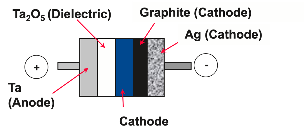
Figure 1: Basic Structure of a Tantalum Capacitor
Tantalum capacitors are known for their high capacitance in a small size. A simple planar structure like that shown in Figure 1 would not give that result. Let’s examine the equation for a parallel plate capacitor to see how tantalum capacitors can achieve these high capacitances in a small volume. Equation 1a is the governing expression for the capacitance of a parallel plate capacitor.
$$ C = K\epsilon_{0} \times \frac{A}{d} \tag{1a}$$
where ϵ0 is the permittivity of free space, K is the dielectric constant relative to a vacuum (which is taken as 1), A is the area between the plates, and d is the thickness of the dielectric. Equation 1a can be put in a more useful form by multiplying both sides by the rated voltage of the capacitor, Vr and dividing by the volume (Vol).
$$\frac{CV_{r}}{Vol} = K\epsilon_{0} \times \frac{A}{Vol} \times \frac{V_{r}}{d}\tag{1b} $$
Equation 1b relates the amount of charge at the rated voltage of the capacitor (q = CVr) stored per volume to the fundamental parameters of the capacitor which are the dielectric constant (Kϵ0), the surface area per volume (A/Vol), and the maximum electric field between the conducting plates (Vr/d). The rated voltage of the capacitor is defined as the voltage at which long-term reliability testing is performed.
The relative dielectric constant of tantalum pentoxide is about 26. This is much higher than the dielectric constant of plastic films used in film capacitors (2 to 3) and somewhat higher than the Al2O3 dielectric in aluminum electrolytic capacitors (8 to 10), but much lower than the barium titanate-based dielectrics in Class II MLCCs (on the order of 1000).
The high charge storage per volume is achieved because of the second and third terms in Equation 1b. Commercial tantalum capacitors are manufactured by compressing fine tantalum powder into a porous pellet and then sintering that pellet to interconnect the powder particles to form a high surface area per volume tantalum anode structure. A scanning electron micrograph of such a powder is shown in Figure 2. The primary particles are submicron in size. Typical surface areas might be 2m2/g and the density of the tantalum pellet is around 6g/cm³ which gives a A/Vol on the order of 12m2/cm³ for a state-of-the-art tantalum capacitor.

Figure 2: Scanning Electron Micrograph of Capacitor Grade Tantalum Powder
Tantalum pentoxide dielectrics are also able to withstand high electric fields before breaking down. Tantalum pentoxide thickness is directly related to the anodization voltage—about 1.8 nm of oxide is formed per volt of anodizing voltage1. Thus, the maximum electric field (V/d) that the dielectric can withstand before breaking down is the inverse of this or about 550 V/µm. Typically, the rated electric field is about 2 to 4 times lower than this, so the rated electric field ranges from about 135 to 225 V/µm. This is comparable to the fields that Al Electrolytic and film capacitors operate at and much higher than operating electric field across the dielectric in Class II MLCCs (which are closer to 10 V/µm).
In the previous paragraphs, I’ve described the ‘ideal capacitor’. Real capacitors (including tantalum capacitors) have other electrical characteristics associated with them. Figure 3 shows a model of a real capacitor with its parasitic electrical characteristics. This model is somewhat simplified, but it illustrates some key characteristics.
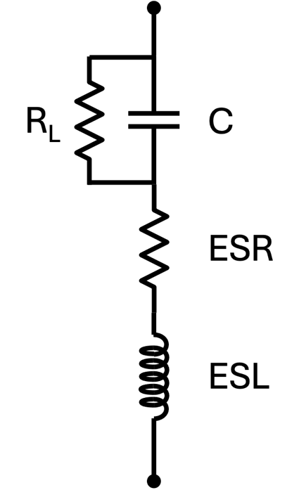
Figure 3: Model of Capacitor with Parasitics
No dielectric is perfect, and all exhibit some leakage of charge. The rate of charge transfer through the dielectric is called the leakage current (sometimes the DC leakage current) and is represented in Figure 3 as a resistance RL (insulation resistance). This resistance is related to the leakage current (IL) by:
$$R_L = \frac{V}{I_L}\tag{2}$$
Where V is usually the rated voltage of the part. The leakage current can degrade circuit performance especially in battery circuits where it can drain energy from the battery. If the leakage current increases over time (due to degradation of the dielectric), then eventually the capacitor can become a short circuit and cease to function or even heat up and damage other parts of the circuit.
Another key parameter is Equivalent Series Resistance (ESR). This resistance limits the rate at which a capacitor can deliver its charge (or energy) to a circuit and the maximum AC current the capacitor can handle without overheating. It is determined by the materials of construction of the capacitor. While I show it as a simple resistor in Figure 3, the ESR varies with frequency and temperature. Significant research and development effort has been expended in the last 50 years in lowering the ESR of solid tantalum capacitors.
An important parameter related to the ESR and to the thermal properties of the capacitor is the ripple current capability. Often tantalum capacitors are used in applications (e.g., filtering on the output of a switched mode power supply) where they are subjected to a time-varying or ‘ripple’ current. Power is dissipated as heat by the capacitor through its ESR:
$$ P = I_{rms\ \ }^{2} \times ESR\tag{3a} $$
where Irms is the root mean square ripple current. The temperature rise of the capacitor is related to this power and the thermal properties of the capacitor by:
$$\mathrm{\Delta}T\ = R_{th} \times P\tag{3b} $$
where Rth is the thermal resistance (°C/W) and ΔT is the temperature rise of the core of the capacitor above ambient (Tcore-Ta). Combining Equations 3a and 3b gives:
$$I_{rms} = \sqrt{\frac{\mathrm{\Delta}T}{R_{th}ESR}}\tag{3c}$$
It is important to keep the maximum temperature of the capacitor below the maximum rated temperature of the capacitor otherwise a failure can occur. For a given temperature rating, the lower the ESR the higher the ripple current that the capacitor can handle. Often the limiting factor in the number of tantalum capacitors required is not the total capacitance but the ESR and ripple current rating.
The Equivalent Series Inductance (ESL) is determined primarily by the geometry of the capacitor such as size and how the leads from the tantalum anode and the cathode are connected to the circuit. It determines the frequency range over which the capacitor is effective as a capacitor. At frequencies higher than the resonant frequency, the capacitor no longer acts as a capacitor but becomes inductive.
The model shown in Figure 3 is only an approximation of the behavior of a tantalum capacitor because capacitance, ESR, and ESL are frequency-dependent. The frequency dependence of ESR is due to the distributed nature of the cathode resistance in the porous anode pellet, the AC resistance of the dielectric, and the skin effect on resistance at higher frequencies. Manufacturers of tantalum capacitors have developed SPICE models to capture these effects2 and these models are available on their websites3 for online calculation or as parameters to incorporate in customers’ modeling software.
Manufacture
The internal structure of a solid tantalum capacitor is shown in Figure 4, and the manufacturing flow is shown in Figure 5. The production process starts with the high-surface-area tantalum powder which is mixed with a small amount of organic binder or lubricant and pressed into an anode pellet. Most commonly, a tantalum wire is inserted in the anode pellet during pressing (but in some processes it is welded to the anode pellet after sintering). Typical press densities are in the range of 5.5 to 7g/cm³. Since tantalum metal has a density of 16.65g/cm³, the porosity of these pellets is in the range of ~57-67%. The binder is then removed by either thermal decomposition or by washing it out. The tantalum particles in the anode are then sintered together under a vacuum to form a robust electrical connection between the particles and between the particles and the tantalum lead wire. The sintering temperature depends on the particle size but 1100-1700°C are typical for the range of powders used today. The anode pellets shrink by 5-10% (typically) during this sintering process. Tantalum always has a native oxide film of tantalum pentoxide present when it is exposed to an air atmosphere. During sintering, oxygen from the native oxide film (a couple of nanometers thick) is driven into the bulk of the tantalum. The anode pellets are cooled under an argon blanket and air is gradually introduced to re-form a passivating native oxide layer. The reaction of un-passivated tantalum with the oxygen in air is highly exothermic and the introduction of air needs to be done in a controlled manner especially for higher surface area powders to avoid over oxidizing or burning of the anode pellets.
The tantalum pellets via the lead wire are then attached to a conductive bar to carry them through the subsequent electrical and chemical processing steps. This bar is made from an aluminum or steel alloy. An insulating protective coating or washer is applied to the tantalum lead wire to prevent cathode material from migrating up the wire to where the wire will be welded to the external anode lead; otherwise, there is a potential for the anode and cathode to form a short circuit. The pellets are then dipped in an electrolyte solution (typically dilute phosphoric acid) to anodize some of the tantalum to ‘form’ the Ta2O5 dielectric. A common profile for anodization is to apply a constant current to the parts until they reach the anodization voltage and then hold at the anodization voltage for some period of time until the residual current drops to a low value. Figure 4 shows the particles coated with this dielectric material. Anodization voltage depends on what the rated voltage the capacitor will have. They are typically in the range of 10 to 200Vf for 2.5 to 75Vr capacitors. At 1.8 nm/V this means that dielectric thicknesses are in the range of 18 to 360nm.

Figure 4: Internal Structure of a Solid Tantalum Capacitor
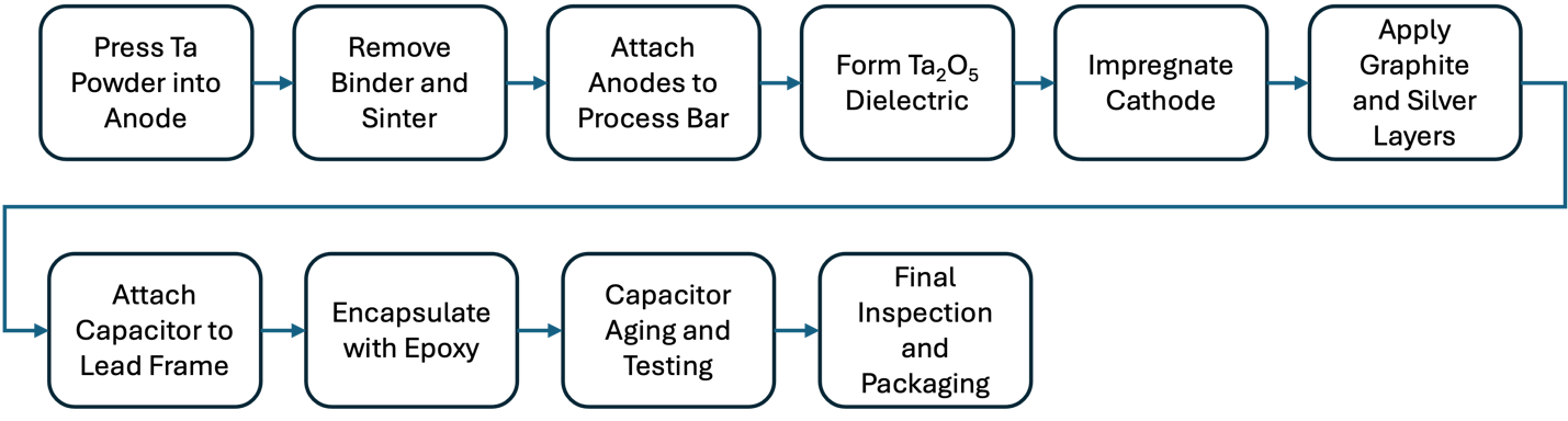
Figure 5: Tantalum Capacitor Manufacturing Flow for Surface Mount Devices
After formation of the dielectric, the cathode electrode is deposited. The original cathode used in the solid tantalum capacitor invented at Sprague Electric4 and at Bell Labs5 was manganese dioxide (MnO2). To fully utilize the internal surface area of the tantalum pellet, the manganese dioxide must make contact throughout the entire pellet with the dielectric. To accomplish this, manganese nitrate solution is soaked into the pellet and then it is converted to manganese dioxide by heating at ~260°C in an air or moist air atmosphere:
Mn(NO3)2 → MnO2 + 2NO2 (4)
The newer type of cathode is an intrinsically conducting polymer which are polymers with a conjugated backbone that are ‘doped’ with an ionic material. In these materials, the polymer itself is conductive unlike metal-polymer composites which owe their conductivity to metal fillers. These were discovered in the 1970s6 and applied to aluminum7 and tantalum capacitors8 by the mid-1990s. The primary reason for using these materials is they are much more electrically conductive than manganese dioxide and the resulting tantalum capacitors have lower Equivalent Series Resistance (ESR). There are many types of conductive polymers (see Figure 6), but polypyrrole (PPy) and polyethylenedioxythiophene (PEDOT) are the ones used in tantalum capacitors. They can be deposited inside the tantalum pellet by electrochemical oxidation of a monomer/dopant, chemical oxidation of a monomer/dopant, or by using a dispersion of already polymerized material.
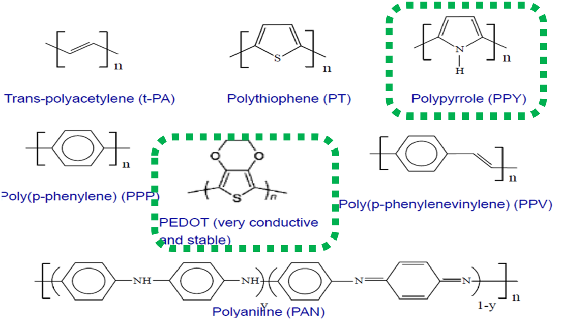
Figure 6: Intrinsically Conducting Polymers
Multiple depositions are required to fully impregnate the cathode materials throughout the anode pellet and to contact as much of the dielectric surface as possible. In between deposition steps, the capacitors are ‘reformed’ by placing them back in a similar electrolyte used for anodization and applying a voltage. This step is necessary to repair any damage done to the dielectric during the cathode deposition (due to temperature, chemical attack, etc.).
For both types of cathodes, cathode electrode material is deposited also on the outside surface of the pellet. After this, the outside is overcoated first with a carbon paint and then with silver paint. These paints are mixtures of carbon or silver with an organic binder and solvent. The solvent thins the mixture so the paints can be applied by dipping. The purpose of the carbon is to prevent any reaction between the silver and the manganese dioxide or conductive polymer. The silver provides a highly conductive path around the outside of the capacitor.
At this point, the basic capacitor structure (two conductive plates separated by a dielectric) is formed (Figure 1), but this ‘bare’ capacitor would not be able to withstand the stress of attachment to a printed circuit board, reflow soldering, and the mechanical and environmental stress in typical electronics applications. A robust means of electrical attachment and mechanical and environmental protection must be provided. The first solid tantalum capacitors were the through-hole or leaded type. Figure 7(a) shows a hermetically sealed leaded tantalum capacitor where the silver paint is attached to a metal can via solder, a wire is welded to the can to form the cathode lead, and the anode tantalum wire is welded to a solder coated nickel wire. Today, over 90% of tantalum capacitors are of the surface mount type which is shown in Figure 7(b). For this type, the silver paint on the cathode side is attached to a metallic lead frame using a silver adhesive. The anode tantalum wire is welded to the opposite side of the lead frame. The capacitor (excluding the external lead frame) is covered with a silica-filled, non-conductive epoxy usually by molding at temperatures around 165°C. At this point in the process, the capacitors may be marked with their capacitance, voltage, date codes, and possibly manufacturer ID. The marking process is done by laser or by ink-printing.
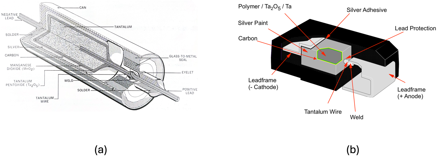
Figure 7: Tantalum Capacitor Packaging (a) Leaded Hermetic Pkg with Manganese Dioxide Cathode (b) Surface Mount Pkg with Polymer Cathode
The packaging steps described in the previous paragraph can place considerable mechanical and thermal stress on the capacitor element’s dielectric. The leakage current after these packaging steps is much higher than the catalog specification. The leakage current is reduced through a process called aging where a voltage is applied to the capacitor for some period of time. One of the reasons this is effective is that the manganese dioxide and conductive polymer cathodes have the property of ‘self-healing’ where they are converted to non-conductive materials at any defect (leakage) site in the dielectric. Figure 8 shows the self-healing reactions. Defects in the dielectric can include cracks due to the thermal and mechanical stresses from packaging and areas where the dielectric did not grow properly due to impurities in the tantalum powder (such as metals like nickel and carbon). The leakage current flowing through a small defect generates heat due to Joule heating. In Figure 8(a), manganese dioxide is converted to a lower manganese oxide such as Mn2O3 at temperatures around 500°C. These lower manganese oxides are not conductive and form a non-conductive ‘plug’ at the leakage site which prevents further leakage current flow. Figure 8(b) shows the process for conductive polymers; they are also thought to form non-conductive plugs by de-doping or by burning away the polymer through thermal decomposition (at lower temperatures than for manganese dioxide). This also provides some insight on why much more conductive cathode materials like copper, nickel, or silver are not placed in direct contact with the dielectric—these metals don’t vaporize until very high temperatures which would destroy the capacitor.
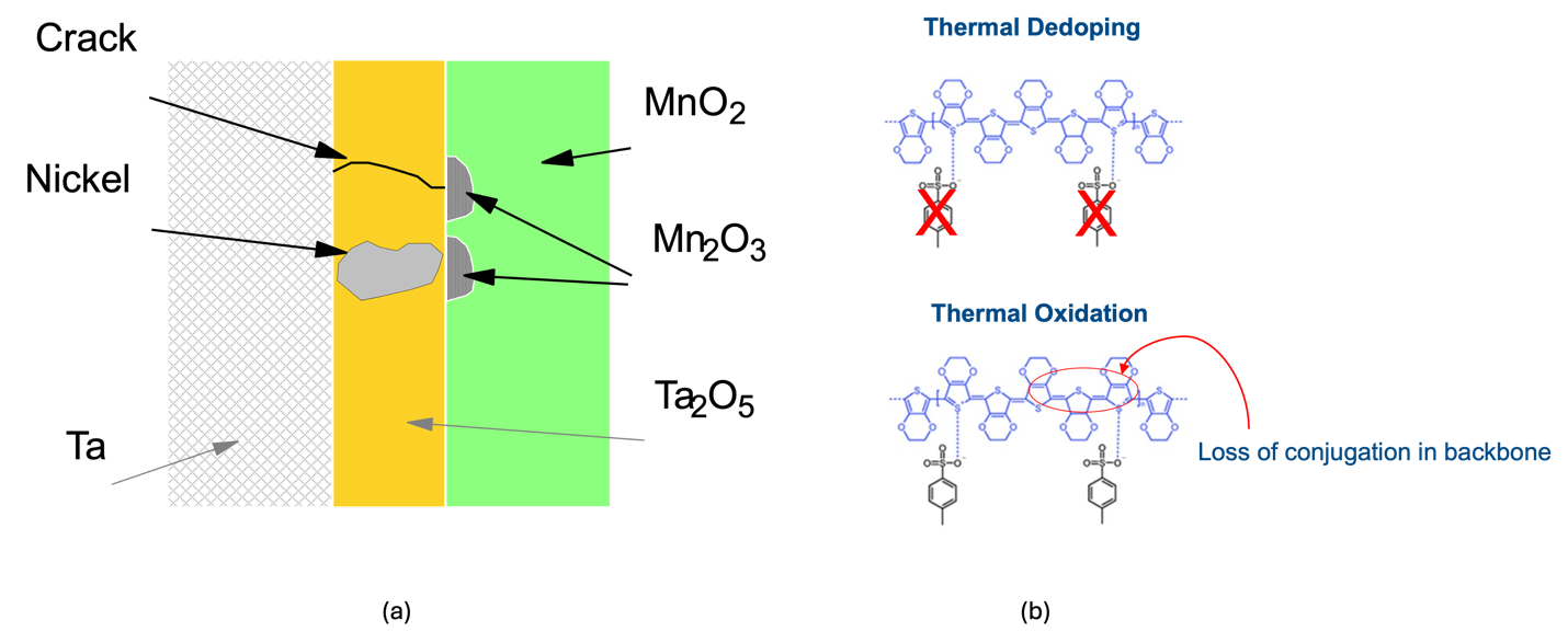
Figure 8: Self-Healing of at Cathodes in Tantalum Capacitors (a)MnO2 Cathode (b) Conductive Polymer Cathode
After aging, the capacitors are then tested for conformance to their electrical specifications. Some non-destructive tests are done on 100% of the capacitors. These include capacitance (at 120Hz), dissipation factor (at 120Hz)9, ESR (at 100kHz), and leakage current (at rated voltage and room temperature and, sometimes, at elevated temperature). For some capacitors, surge current is applied, and leakage current is checked once again. Capacitance must be within a tolerance band of the nominal capacitance—±20% and ±10% tolerances are common. DF, ESR, and leakage current are tested against a maximum limit with a ‘guard-band’ applied against the catalog specifications. Capacitors that don’t meet the electrical specification are cut out and discarded in the reject bin. The capacitors are also inspected visually (either by trained production workers or by AOI) for defects such as pinholes and show-throughs in the epoxy case. For some specialty applications (such as medical), capacitors may also undergo X-Ray inspection to look for any misalignments inside the package.
Some destructive testing is performed on a sample of capacitors from each lot. The most common test in this category is surface-mount testing where the capacitors are mounted to a printed circuit board and then sent through a reflow-oven to attach them. After reflowing, capacitance, DF, ESR, and leakage current are measured. If any of these are out of specification, the lot may be reprocessed or scrapped. Other sampling tests may include breakdown voltage and accelerated life-testing.
After testing, the capacitors undergo final packaging to be in a form that is ready to use by the customer. For surface mount capacitors, this means that the leads are bent into their final position underneath the body of the capacitor and then capacitors are put into a carrier-tape which is wound around a reel. There may be some further electrical testing at this point to verify that the capacitance is the correct value and that no damage was done to the capacitor in this lead forming step (by measuring DF). The reels may be put directly in boxes, or they may be put into ‘moisture-bags’ to keep the capacitors dry (this is especially common for the conductive polymer types).
Capacitor Landscape
Tantalum capacitors form a region of the capacitor landscape which is illustrated in Figure 9 where capacitance and voltage regions for the major types of capacitors are shown. Solid tantalum capacitors, for use in commercial applications, typically have capacitances ranging from approximately 1µF to 1500µF and voltage ratings from 2.5V to 125V. The 125V rated voltage is a limitation on the anodization of tantalum to tantalum pentoxide, as tantalum pentoxide has the tendency to form a rough crystalline dielectric instead of a conformal amorphous dielectric as voltage increases. Aluminum oxide does not have this same limitation (the crystalline aluminum oxide dielectric formed at higher voltages is conformal) and aluminum-polymer capacitors are available up to approximately ~250V and aluminum wet electrolytic capacitors up to approximately ~700V. Most circuit designers also de-rate tantalum capacitors from their rated voltage. Typically, the manganese dioxide type would be used in circuits at 50% of rated voltage and the conductive polymer types at 80 to 90% of their rated voltage. There is further de-rating for temperatures above 85°C.
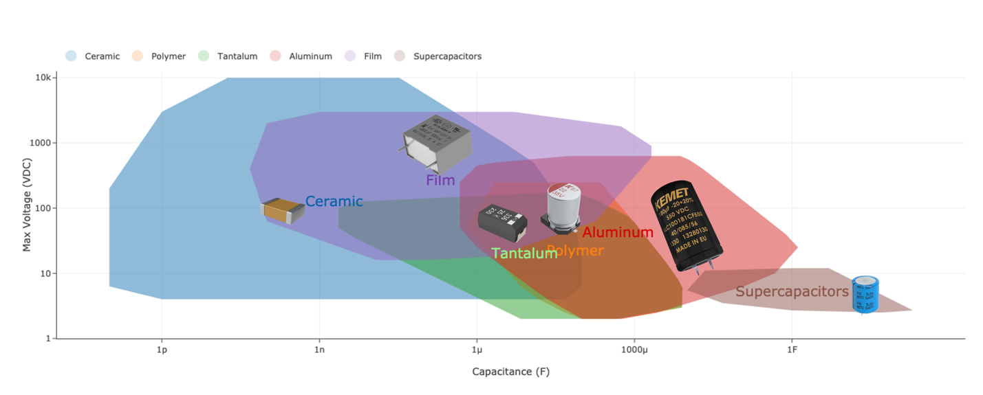
Figure 9: Capacitor Landscape
The maximum capacitance is limited by the ability to impregnate the cathode material uniformly throughout the volume of the anode. As seen previously, the tantalum anode structure is “sponge-like”, creating a rather torturous path for the cathode to penetrate into the anode, especially as powder charge keeps increasing. As the anode becomes too large, it is hard to coat all the dielectric. For larger capacitances, aluminum capacitors are usually specified. On the lower capacitance side, tantalum capacitors compete with ceramic (MLCC) capacitors. For capacitance values 1µF or less (or even 22µF or less), MLCCs are usually a more cost-effective solution unless some specific tantalum capacitor property (like low capacitance dependence on voltage or temperature) is needed.
Technology Progress
Tantalum Powder, Wire, and Anode Technology
Equation 1 illustrated that the area term is one key to obtaining the high capacitances in small package sizes for tantalum capacitors. There has been significant advancement in increasing the surface areas of tantalum powders over the last 50 plus years. Instead of specifying the surface area, powder manufacturers specify the specific charge or CV/g of the powder. Here V is the anodization or formation voltage of the anode—Vf. The units of CV/g are µF-V/g (µColoumbs/g). The CV/g is measured by sintering an anode pellet from the powder, weighing it, anodizing the pellet to a given Vf and then measuring the capacitance in a cell with the anodized pellet as one electrode, and an inert (e.g., platinum or un-anodized tantalum) counter electrode of much higher surface area, and a wet electrolyte (usually dilute phosphoric or sulfuric acid). The capacitance is multiplied by the anodization voltage and divided by the pellet weight to obtain the CV/g. Although this is commonly called the CV/g of the powder, it is really the CV/g of the sintered anode fabricated from the powder, and, thus, is affected by press density and sintering conditions. The CV/g also varies with Vf, so it is important to specify the Vf at which it was measured. Tantalum powder manufacturers will often supply curves of CV/g vs. Vf.
Figure 10 illustrates how tantalum particle sizes have decreased as CV/g has increased from <10,000 in the 1960s to 150,000 and greater today. The powder morphology used is primarily nodular, but powders with a flake morphology are used in some higher voltage capacitors.
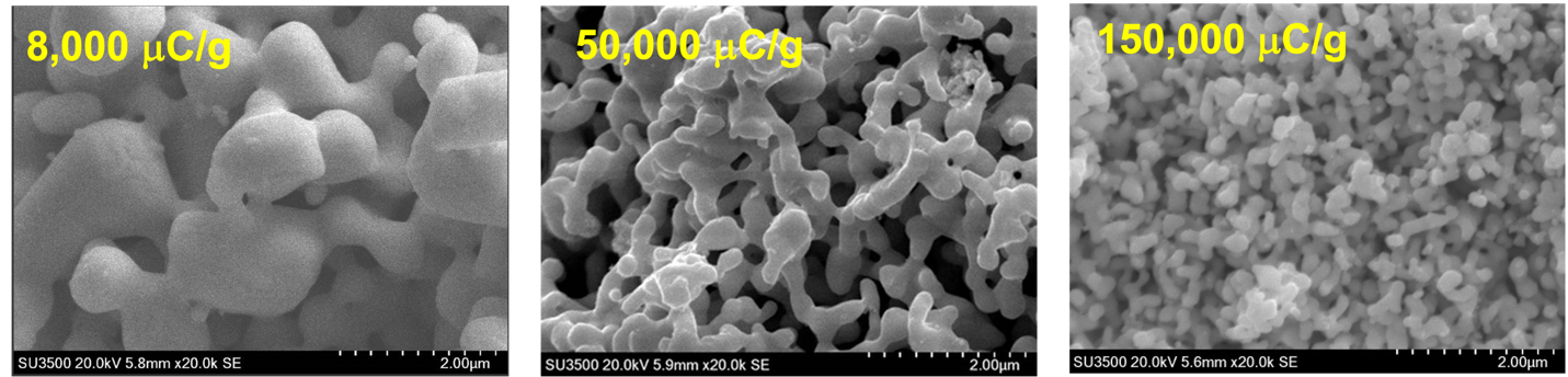
Figure 10: Scanning Electron Images of Tantalum Powders with Increasing CV/g
Figure 11 illustrates a timeline of tantalum powder (anode) CV/g increases and the resulting effect on the miniaturization of the tantalum capacitor10. Powders are available today with CV/g of around 250,000µCoulomb/g.
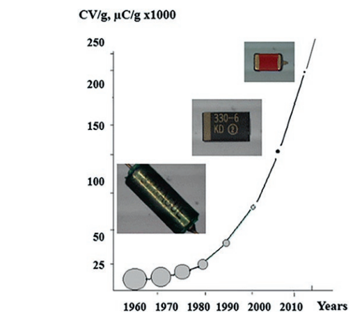
Figure 11: Trend in Tantalum Powder CV/g
We can express CVr/Vola our fundamental measure of how much charge we can put into a given anode pellet volume, as:
$$ \frac{C_{w}V_{r}}{{Vol}_{a}} = \frac{CV_{f}}{g} \times \rho_{s} \times \frac{V_{r}}{V_{f}}\tag{5}$$
Where CVf/g is the specific charge of the anode measured at the anodization voltage (Vf) of the capacitor, ⍴s is the sintered density of the anode and Vr/Vf is the ratio of the rated voltage of the capacitor to its anodization voltage of the capacitor. Here I denote the capacitance as Cw to emphasize that this is the ‘wet’ capacitance measured in an electrolyte (usually phosphoric or sulfuric acid). Writing the equation in this form illustrates several fundamental points:
The powder needs to be able to be pressed, into an anode pellet, at a useful press density. For state-of-the-art tantalum capacitors this is roughly in the 5.5 to 7g/cm³ range.
The specific charge is measured at the anodization voltage of the part.
The ratio of Vr/Vf is a critical part of the equation. It is related to the quality of the dielectric which in turn is related to the powder purity and the anodization conditions. The cathode (manganese dioxide and the type of conductive polymer) also plays a role in determining this ratio. It usually falls in the range of ½ to ¼ for tantalum capacitors that meet reliability requirements for commercial and military specifications.
Powder purity is an important parameter as impurities such as heavy metals (Fe, Ni, Cr), carbon, potassium, magnesium, etc. can prevent the formation of a quality tantalum pentoxide dielectric. Tantalum powder manufacturers have made significant progress in reducing these impurities to ppm levels. Carbon should be less than 50ppm (and preferably less than 30ppm) and heavy metals less than 10ppm each. Oxygen is another impurity. Dr. Yuri Freeman and his colleagues at Tel Aviv University studied the role of oxygen on dielectric quality11. The desired oxygen level depends on the surface area (CV/g) of the powder and 3500 ppm/(m2/g) is a generally accepted desirable level. Oxygen can be on the surface (as the native tantalum pentoxide film) or in the bulk of the tantalum (in the tantalum crystalline lattice). Unlike the other impurities mentioned above which are almost impossible to remove from the powder, the oxygen level can be tuned to some degree in processing by the tantalum powder or capacitor manufacturer. Powder manufacturers may also add small amounts of elements such as nitrogen or phosphorous to modify the oxygen uptake or sintering behavior of the powder.
Tantalum capacitors with voltage ratings >16V have seen significant growth in the last several years as higher voltage rails are used to limit I2R losses in power delivery systems. Capacitor manufacturers want to use the highest CV/g possible at the higher voltages. All tantalum powders have a distribution of particle sizes and sinter neck sizes between particles, and the smallest particles and sinter necks are consumed by the dielectric formation and, therefore, don’t contribute to capacitance at higher anodization voltages. Manufacturers have developed powders that have narrower particle size distributions and may have lower CV/g at lower anodization voltages but have less of a decrease of CV/g with an increase in anodization voltage12. The particle and neck size can also be modified by special anode pellet sintering techniques, such as sintering in the presence of magnesium13.
Tantalum powders must be able to be fabricated into anode pellets which is conventionally done by flowing the powder into a die and then compressing the powder within the die. As tantalum powders became finer (higher surface area or CV/g), flow characteristics decreased, and it became more difficult for the powders to flow into the die. This issue is overcome by forming the fine particles into larger agglomerates in an agglomeration/sintering step. Powder manufacturers also adjust the bulk (Scott) densities of the powders in this step so that manufacturable compression ratios can be used during the pressing of the powder in the die.
Organic binders help with powder flow but can raise carbon levels in the final anode. Binders that are removed by water washing (like stearic acid) can result in anodes with carbon levels near that of the incoming powder. For binders removed by thermal means, carbon levels in the anode pellet can exceed 100ppm.
The tantalum lead wire is also an important part of the capacitor. The wire manufacturing process starts with “met-grade” tantalum powder which is compressed into a tantalum cylinder. The cylinder is then drawn down through increasingly smaller dies to the final wire size. Some wires are doped with small amounts of dopants to modify characteristics such as tantalum grain size in the wire. Wire may also be annealed which results in a ‘softer’ wire which may be desirable for some manufacturing processes.
Dielectric Technology
The electrochemical oxidation of tantalum, to tantalum pentoxide can be written as:
Ta + 5H20 → Ta2O5 + 5H2 (6)
The reaction is illustrated schematically in Figure 12. Oxygen from the water diffuses inward and tantalum diffuses outward to form the tantalum pentoxide. Hydrogen ions are produced at the reaction surface and migrate to the cathode where hydrogen gas is generated. The cathode plate is usually a stainless-steel alloy. Because of the difference in density and molecular weight between the oxide and the tantalum, the oxide grows partially inward and also outward from the original tantalum interface. This has implications for the porosity of the anode pellet and for potential electrical disconnection when tantalum metal is fully consumed.
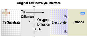
Figure 12: Tantalum Anodization to Tantalum Pentoxide
Figure 13 schematically illustrates the interior of a tantalum anode pellet before and after anodization. The sintered tantalum particles can be (approximately) represented by spheres connected by thinner necks that form on sintering. The necks are about 2/3 the diameter of the spheres. As stated above, anodization proceeds both inward and outward from the original tantalum surface, so the less dense oxide reduces the porosity of the anode pellet. At higher anodization voltages, this reduction in porosity can have a significant impact on the ability to impregnate the cathode material as well as the ESR of the capacitor. The tantalum in the necks will be consumed over some range of anodization voltages (there is a distribution of particle and neck sizes) and this is one of the factors responsible for the CV/g reduction with increasing anodization voltages—where the necks are ‘formed through’ the regions become electrically disconnected and no longer contribute to the capacitance.
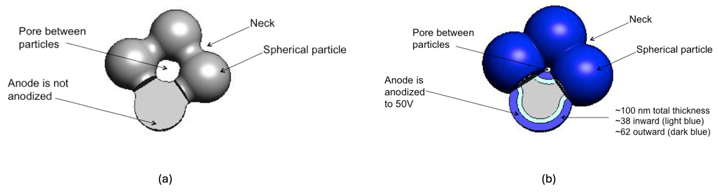
Figure 13: Tantalum Anode Structure (a) Before anodization (b) After anodization
While Equation 5 looks simple, there are a lot of pitfalls to be navigated when forming a high-quality tantalum pentoxide dielectric film, and maintaining that quality through subsequent capacitor processing and application. The desired tantalum pentoxide structure for a dielectric is amorphous as shown in the transmission electron micrograph (TEM) in Figure 1414.
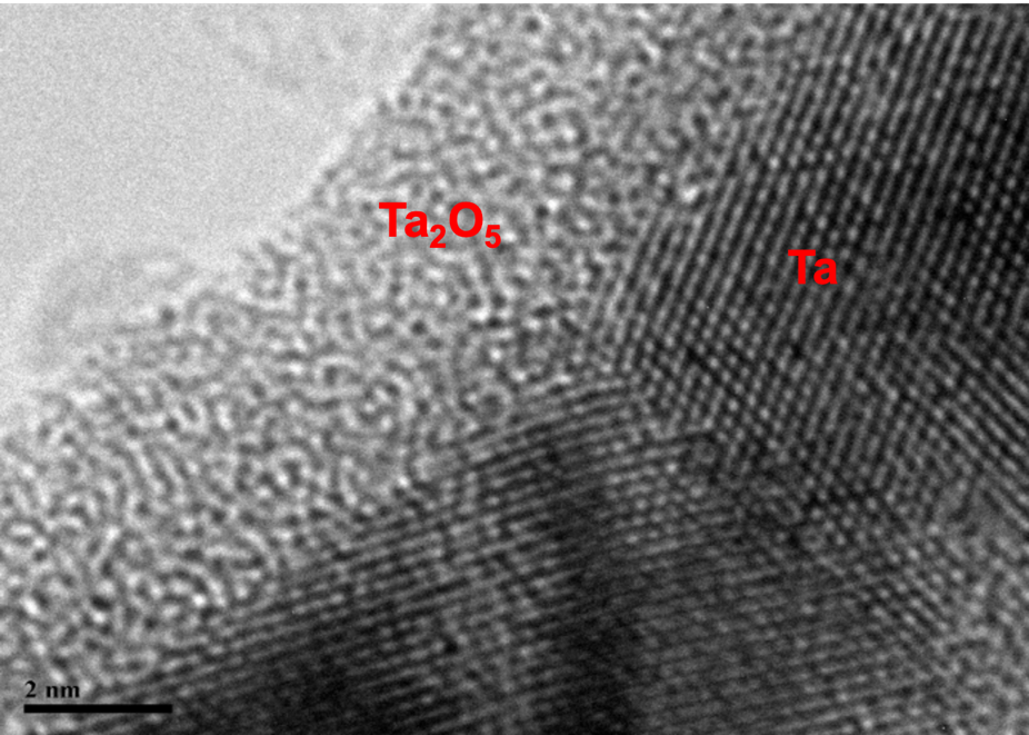
Figure 14: The Formation of an Amorphous Tantalum Pentoxide Dielectric on a Crystalline Tantalum Substrate
The amorphous form of stoichiometric tantalum pentoxide is not thermodynamically stable and considerable effort in research and development has gone into the materials science of stabilizing a stoichiometric, amorphous form of the tantalum pentoxide when it is initially formed through anodization, throughout the fabrication of the capacitor, and later when the capacitor is used in the electronic circuit.
When stoichiometric tantalum pentoxide is in contact with the tantalum in the anode pellet, it will lose oxygen to the tantalum metal and oxygen vacancies will form in the oxide:
Ta + Ta2O5 → Ta(O)x + Ta2O5-x + xVo2+ + 2xe-(7)
The stoichiometric form is an excellent insulator (dielectric) while the oxygen vacancies in the Ta2O5-x form make it a semiconductor which can cause an increase in leakage current, eventually causing short circuit through breakdown of the dielectric. This reaction is accelerated by heat and occurs during the conversion of the manganese nitrate to manganese dioxide, as shown previously, in Reaction 4 and during the operation of the capacitor under temperature and voltage. It is also important to note that if too much oxygen diffuses into the tantalum, this can also have a detrimental impact especially on the tantalum lead wire which can become brittle.
This failure mechanism was recognized early on in solid tantalum capacitor development, and Tripp and his co-workers at Sprague Electric published a series of papers outlining a scheme for reducing the driving force for Reaction 715. The basic scheme is shown in Figure 15. In the first step, the dielectric tantalum pentoxide is formed electrochemically, as by Reaction 6. Subsequently, the capacitor is subjected to a heat treatment to drive some oxygen into the tantalum metal. This Ta(O)x layer forms a barrier to oxygen diffusion in later processing and operation of the capacitor. Since part of the tantalum pentoxide film is depleted of oxygen in this heat treatment step, a second anodization is performed to restore the oxide to its stoichiometric state.
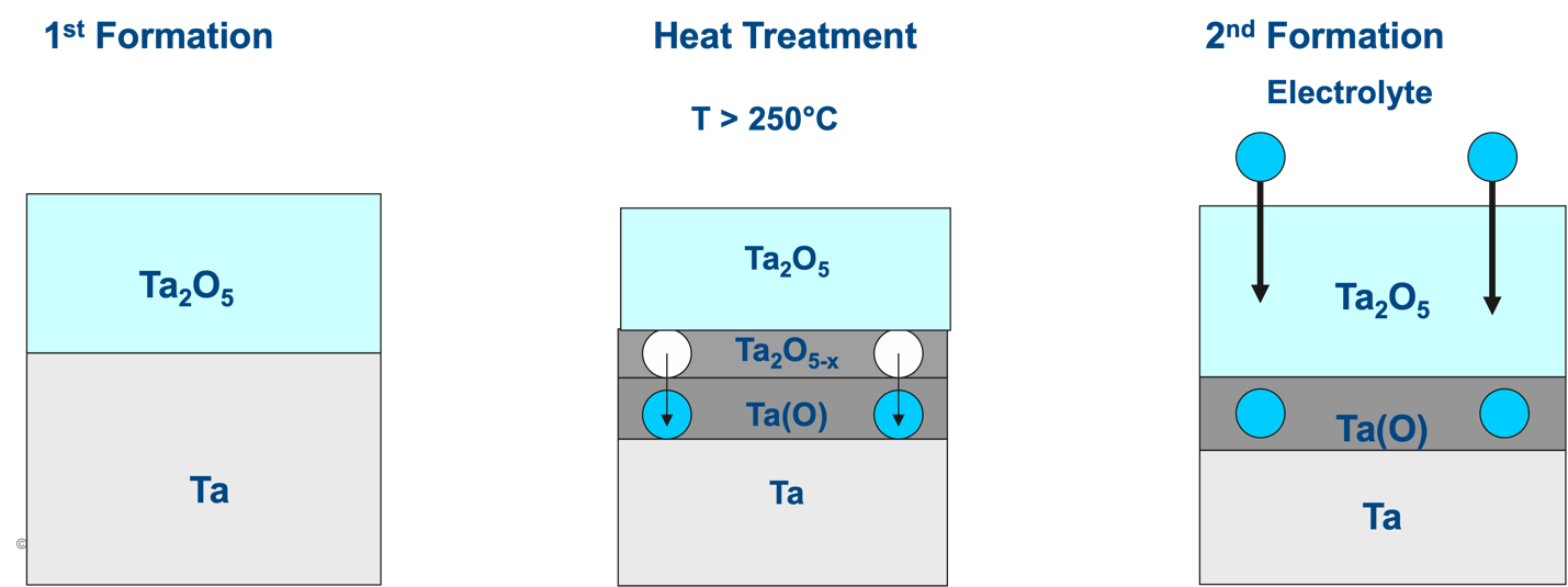
Figure 15: Stabilization of Tantalum Pentoxide Dielectric Film Against Oxygen Migration
Gerhart Klein at P.R. Mallory later extended the understanding of the heat treatment of tantalum in contact with an oxide film and carried out experiments under vacuum16. This heat treatment and second anodization is effective at stabilizing the dielectric against oxygen migration, but it is a careful balancing act to drive the right amount of oxygen into the tantalum metal, and capacitor manufacturers have developed proprietary recipes to optimize the temperature, time, and atmosphere.
Impurities in the tantalum metal powder such as carbon and transition metals (e.g., Fe, Cr, Ni) inhibit or prevent the formation of the amorphous tantalum pentoxide dielectric film. Figure 16 illustrates this for a carbon inclusion in tantalum17. Where carbon was present, the dielectric did not deposit, and a ‘hole’ was left in the dielectric. Through this hole the cathode material could directly contact the tantalum metal forming a short circuit. If these defects are too large or too numerous, the healing mechanism shown in Figure 8 may not be effective.
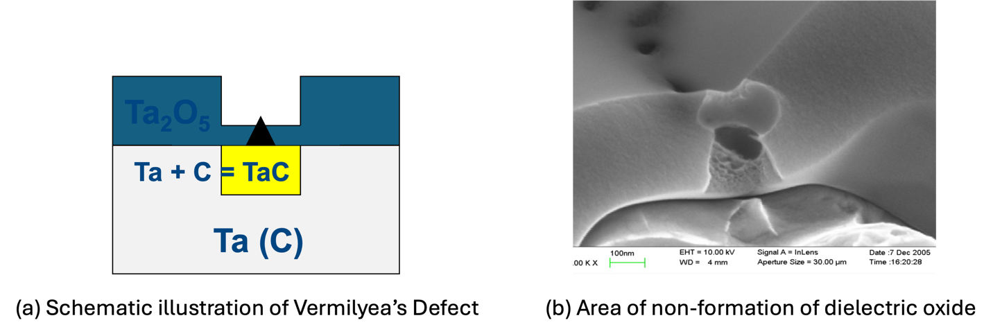
Figure 16: Defect in Dielectric Film Due to Carbon Impurity
The crystalline form of tantalum pentoxide is more thermodynamically stable than the amorphous form and care needs to be taken that the amorphous dielectric film doesn’t crystallize during the anodization step or in subsequent capacitor processing or use. Crystalline tantalum pentoxide grows perpendicular to the surface and will form ‘blisters’ that disrupt the dielectric film because of its density difference with the amorphous oxide. This results in sites of high leakage current. This contrasts with aluminum oxide which forms a conformal crystalline dielectric, and high voltage aluminum oxide dielectrics have a conformal crystalline outer layer and an amorphous inner layer.
There are several conditions that promote the growth of crystalline tantalum pentoxide. If the oxygen level in the tantalum metal is too high, then crystalline nuclei can form on the surface (Figure 17)18. These crystals may not be a problem at the start of the capacitor’s lifetime, but they can grow under the influence of heat and electric field (Figure 18). Eventually, the crystalline inclusions will grow large enough to disrupt the amorphous tantalum pentoxide dielectric, resulting in sites of high leakage current. If these sites are too large or numerous, then self-healing may not occur, and the capacitor will fail.
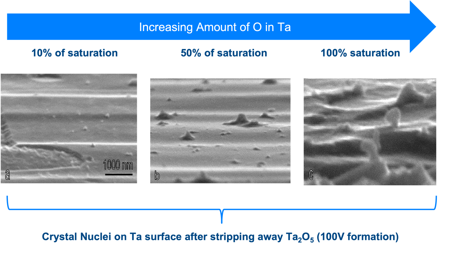
Figure 17: Crystal Nuclei on Ta at Different Oxygen Levels
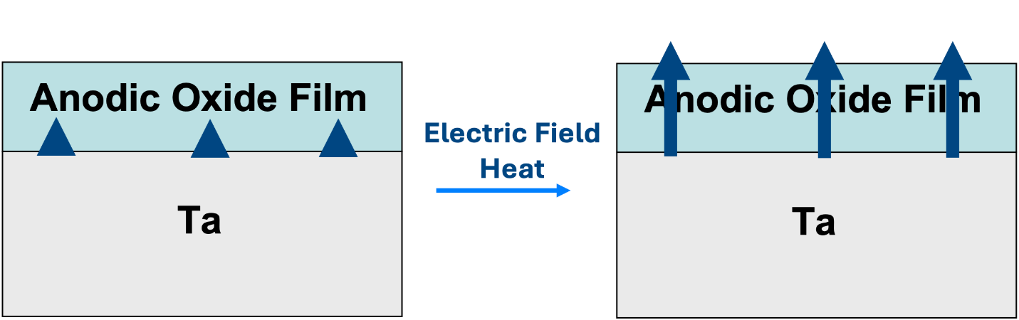
Figure 18: Growth of Crystalline Tantalum Pentoxide
Higher anodization voltages also favor the formation of crystalline dielectric. Figure 19 shows a crystal of tantalum pentoxide deposited on the amorphous dielectric surface. These crystals can disrupt the amorphous film, resulting in failure sites during capacitor manufacture, and they can grow during capacitor use and cause failures later in a capacitor’s lifetime. The crystals can form on the tantalum lead wire as well as on the powder. This is related to voltage as well as the heat generated in the interior of the anode pellet during high voltage anodization. This is a major reason why anodization voltages are limited to ~200V especially for larger anode pellets.
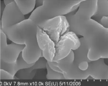
Figure 19: Crystalline Tantalum Oxide
Soon after the invention of the solid tantalum capacitor, it was discovered that anodization in phosphoric acid improved the initial quality of the dielectric film and lifetime of the capacitor19. During anodization in phosphoric acid, phosphorous is incorporated into the outer portions of the dielectric film. Later Sloppy and Dickey extended the mechanistic understanding of this anodization system20. The electrolyte systems are predominantly aqueous (as water is the source of oxygen for the dielectric film). Often ethylene glycol or, more recently, polyethylene glycol are added. This is to retard evaporation (anodization is usually performed at ~60-85°C) and to improve heat transfer. Ethylene glycol appears to play other roles as it is also seen to improve dielectric quality especially at higher anodization voltages.
Phosphoric acid-based electrolytes served and continue to serve as the main system for anodization of tantalum to tantalum pentoxide. However, as powder surface area (specific charge, CV/g) increased, they began to show some limitations. Melody and co-workers developed more conductive electrolytes based on slightly alkaline phosphate salt systems that give better anodization quality for high charge powders21. He also developed a system where tetraglyme was substituted for (poly)ethylene glycol which allowed anodization to be performed below room temperature which reduced the maximum temperature (and, therefore, crystallization) problem at high anodization voltages22.
The outside surface of the anode pellet is the part of the capacitor most susceptible to mechanical damage, especially in the later manufacturing steps of packaging. Forming a higher voltage (thicker) dielectric can help mitigate some of this damage. To anodize only the outside to a higher voltage, a weak acid or salt of a weak acid like borate23 or acetate24 are used. The ionic form becomes the non-ionically conductive undisassociated acid form in the interior of the anode pellet due to build-up of H+ ions in the interior. Only near the outside of the anode pellet where H+ can be transported away quickly does anodization occur. This process is commonly called dual or flash formation.
Cathode Technology
As mentioned previously, the solid tantalum capacitor with the manganese dioxide cathode was invented in the late 1950s almost simultaneously at Sprague Electric Company and at Bell Laboratories. In the patent dispute over inventorship, eventually Sprague prevailed, and the market for this type of capacitor grew rapidly because its high capacitance density, all solid-state construction, and high reliability. These characteristics made it particularly useful in aerospace applications and in the growing electronics industry built around the development of the transistor and the integrated circuit.
A disadvantage of manganese dioxide is its relatively low conductivity of around 0.1 to 1 S/cm. At the frequencies of use for tantalum capacitors in filtering, decoupling, and bypass applications, manganese dioxide dominates the contribution to ESR25. Depending on the size, tantalum capacitors with manganese dioxide cathodes can have ESR ranging from around 100mΩ to several ohms. High ESR negatively affects the performance of the capacitor in the circuit, especially as clock speeds increased and voltage levels decreased. As mentioned earlier, it also limits the ripple current rating of the capacitor. By the early 1990s, this started to become a limiting factor which necessitated using multiple capacitors in parallel to achieve target ESR and ripple current levels. This raised the cost of the tantalum capacitor solution as well as board space requirements. This went against the trends of decreasing cost and increasing miniaturization of electronic devices.
Significant inventive effort was expended from the 1970s to 1990s to overcome the high ESR of these devices. One path was to make the manganese dioxide as conductive as possible. β-MnO2 is the most conductive form, and conditions were optimized to produce this form upon the decomposition of manganese nitrate26. This had minimal impact on the ESR. A more promising path was modifying the geometry of the anode pellet(s) to reduce the distance between the cathode in the interior of the anode pellet and the highly conductive silver coating on the surface. Figure 20a shows the Multiple Anode Tantalum (MAT) configuration, which was invented by Piper in 197227, but not commercialized by KEMET Electronics until 1997. Three parts were placed in a parallel connection in a single package. It allowed ESR of large (7343-43) parts to be reduced from about 70-100mΩ to less than 30mΩ. Placing three parts in a package was slow, and if one part was defective, then the entire assembly needed to be discarded. This made these types of parts expensive. AVX (and later KEMET) commercialized the fluted anode (Figure 20b) which put grooves in the anode pellet to reduce path length28. While not as effective as the MAT, it did lower ESR and was a lower cost and more effective solution.
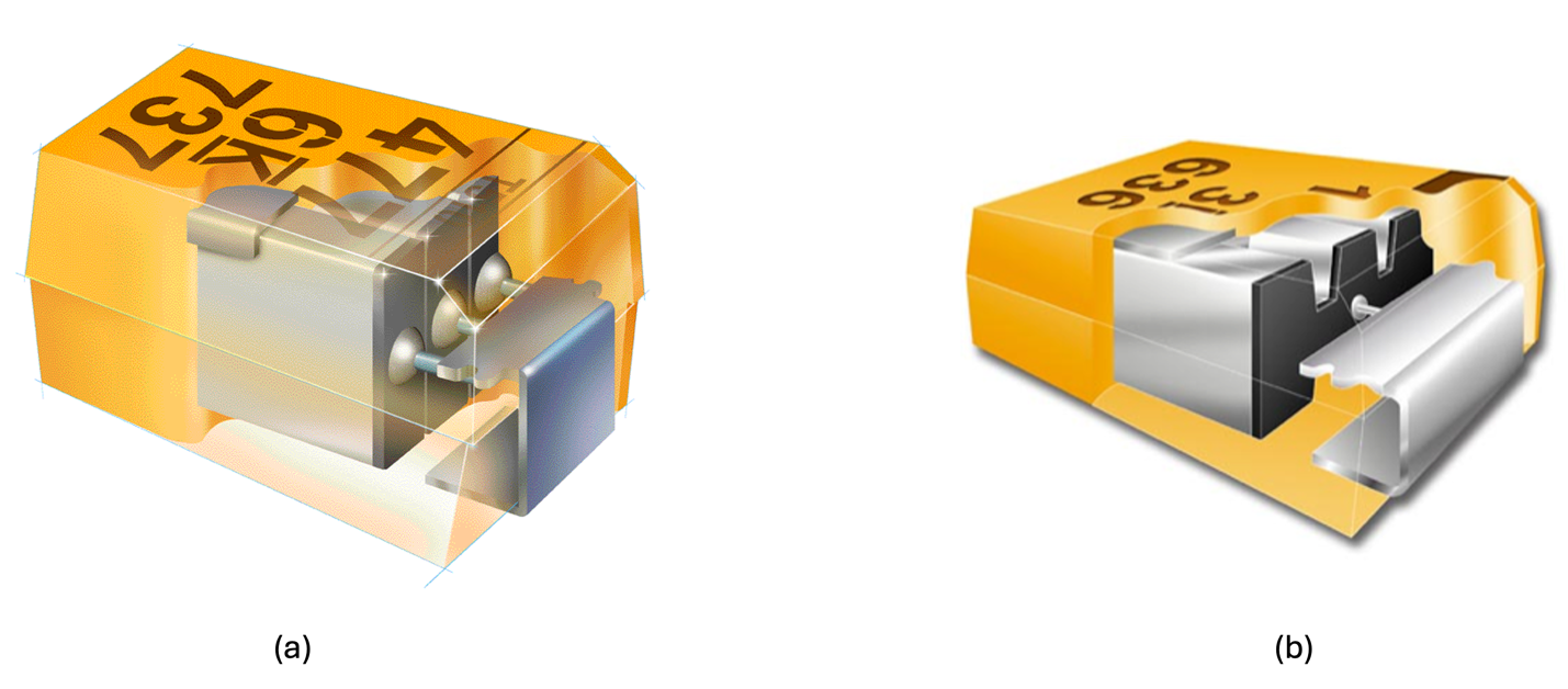
Figure 20: ESR Reduction Through Geometry (a) Multiple Anode Tantalum (MAT) (b) Fluted Anode
Another drawback of the manganese dioxide cathode is its potential to react with tantalum metal if the tantalum pentoxide dielectric is damaged. Under normal conditions, the manganese dioxide will be converted to a non-conductive lower manganese oxide and ‘plug’ any defect in the dielectric. If the defect is too large, then excessive heat will be generated, leading to cracking of the dielectric and the manganese dioxide reacting with the tantalum metal anode. This is a highly exothermic reaction, which can lead to an ‘ignition’ of the part where a flame is emitted from the capacitor and considerable damage to the circuit board and surrounding electronics can occur. It is a rare occurrence under normal circuit operation but is an operational and safety concern.
By the mid-1990s, the manganese dioxide cathode was becoming a barrier to further tantalum capacitor growth because of the factors mentioned above. Leveraging fundamental discoveries made during the 1970s6, a new cathode material was introduced by the Energy Devices Division of NEC in 19945. This material, polypyrrole (structure shown in Figure 6) is an intrinsically conducting polymer with a conjugated backbone and an ionic dopant. Figure 21 shows that the conductivity of these materials is about two orders of magnitude greater than manganese dioxide. NEC branded these devices as the “NEOCAPACITOR”. The polypyrrole was deposited by chemical polymerization with an oxidizer-dopant system. A coupling agent was used to help provide a better interface between the organic conductive polymer and inorganic tantalum pentoxide dielectric29. Due to the difficulty in impregnating polypyrrole through this route and the limited thermal stability of this type of polypyrrole, initial application focused on small capacitors for consumer electronics (the original parts were only rated to 85°C whereas manganese dioxide parts are typically rated to 125°C).
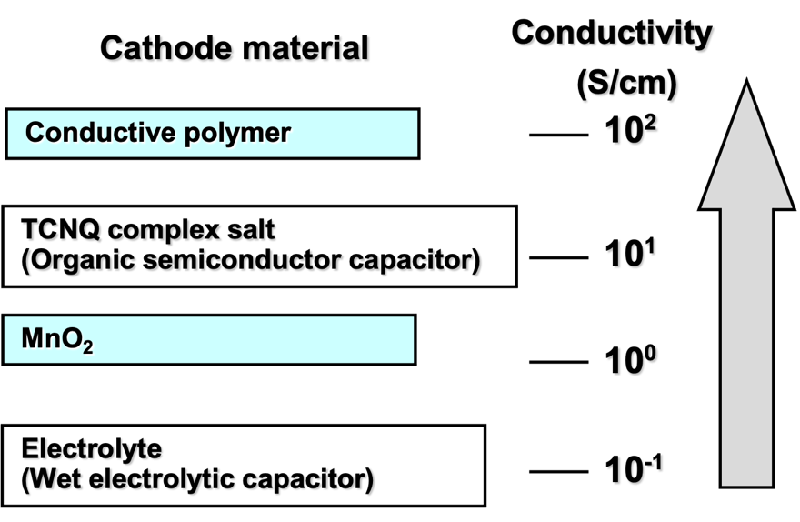
Figure 21: Conductivity of Cathode Materials
NEC followed with a second generation NEOCAPACITOR in 199730 based on the chemical polymerization of PEDOT which was developed by Jonas and his colleagues at Bayer in the late 1980s31. The monomer (EDOT) and oxidant-dopant system (iron(III) p-tosylate) were easier to impregnate and the resulting conductive polymer was more thermally stable than polypyrrole. Figure 22 shows the reaction scheme. KEMET Electronics signed a licensing/partnership agreement with NEC in 1998 and soon large case size tantalum-polymer capacitors capable of temperatures up to 105°C were introduced to the market. ESRs that were only achievable with MAT-manganese dioxide parts were now available with single anode tantalum-polymer, and even single-digit tantalum-polymer MAT parts were introduced. Around this same time, Sanyo introduced a tantalum-polymer part based on electrochemically polymerized polypyrrole, which proved to be more stable than its chemically polymerized cousin.
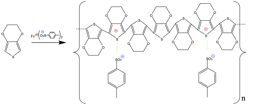
Figure 22: Reaction of EDOT Monomer with Iron(III) Tosylate to form Doped PEDOT
Another advantage of the conductive polymer cathode was its failure mode. The conductive polymer materials don’t contain active oxygen like manganese dioxide, and the highly exothermic ‘ignition’ reaction that can take place on capacitor failure with a manganese dioxide cathode doesn’t happen with a conductive polymer cathode. It should be noted that tantalum-polymer capacitors still fail as short circuits, and a short generates heat which can char the protective epoxy casing.
Yet another advantage of the tantalum-polymer capacitor vs. the tantalum-MnO2 capacitor was a lower derating from rated voltage. A widely recommended derating for tantalum-MnO2 capacitors was 50% of rated voltage, so, for example, a 10Vr capacitor would be used in a 5V circuit. This was mainly to prevent power-on surge failures. Early testing of tantalum-polymer capacitors showed that they had the same failure rates on surge at 80-90% of rated voltage that tantalum-MnO2 capacitors had at 50% of rated voltage32. A 6.3V tantalum-polymer capacitor could be used in a 5V circuit. For higher voltage tantalum-polymer capacitors, the recommendation is to use them in circuits not exceeding 80% of rated voltage.
From their introduction in 1994 to about 2008, tantalum-polymer capacitors were mostly available in ratings of 16V or less (MnO2 cathode parts were available to 50V in surface mount and 125V in special through-hole parts). Tantalum-polymer capacitors of greater than 16V with polymer cathodes deposited by in-situ chemical polymerization (or electrochemical polymerization) were unreliable. The reason for this is illustrated in Figure 2333. While the breakdown voltage (BDV) of MnO2 cathode parts continues to rise with formation (anodization) voltage, the BDV of in-situ chemically polymerized conductive polymer parts saturates at about 50V and depositing a thicker (higher voltage) tantalum pentoxide dielectric has no effect. The rule of thumb is that BDV should be 2.5 to 3 times the rated voltage of the part so, therefore, the 16V limitation.
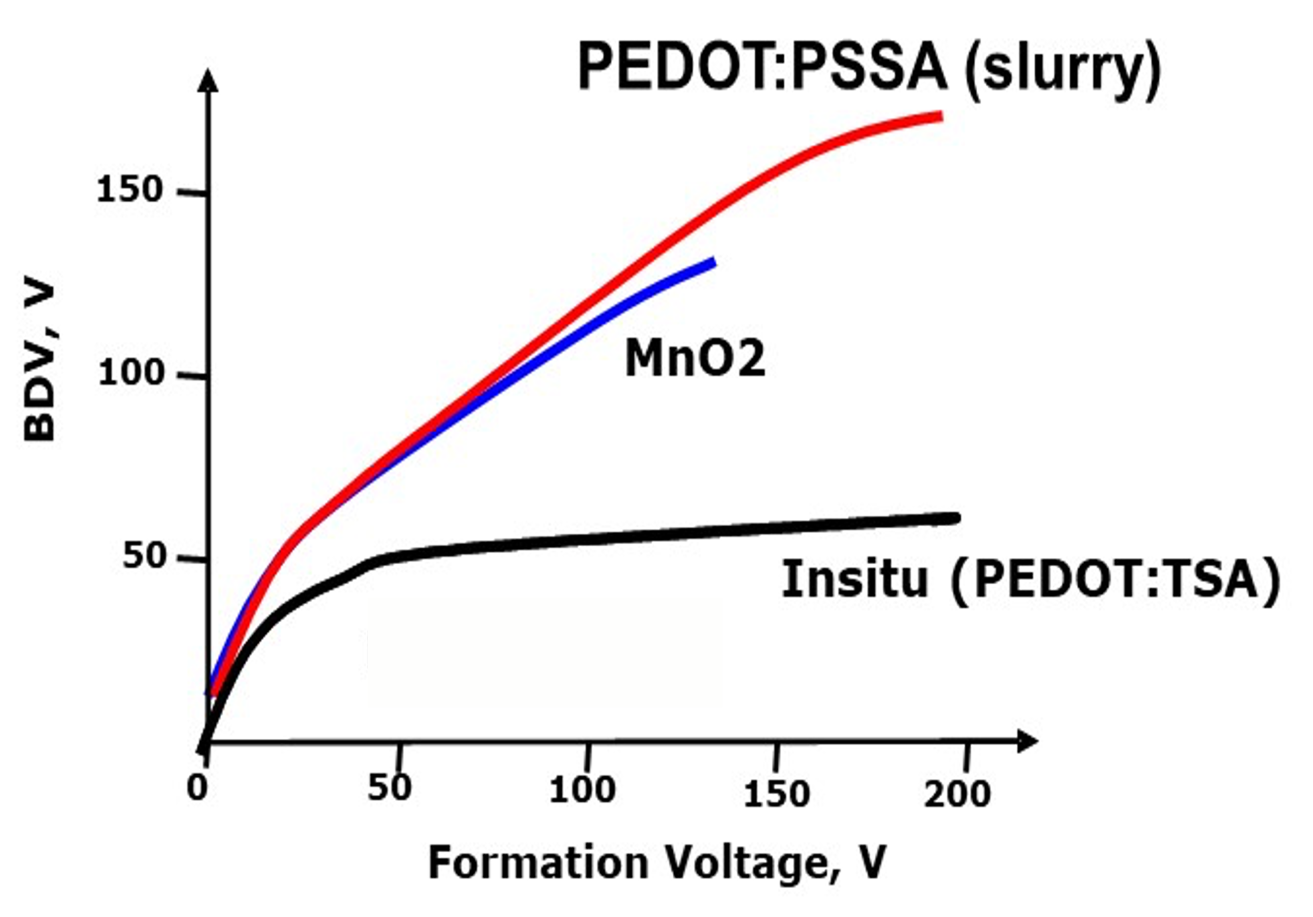
Figure 23: BDV of Tantalum Capacitors vs. Formation Voltage with Various Cathode Systems
While working with a water borne dispersion of pre-polymerized conductive polymer material from Bayer34, Qiu and his colleagues at KEMET Electronics discovered that substituting some of the in-situ chemical polymerization layers with this pre-polymerized dispersion increased the BDV of the capacitor35. This is illustrated in Figure 23 in the line labeled PEDOT:PSSA (slurry). The BDV continues to rise with formation (anodization) voltage even to 150V and above. The structure of this pre-polymerized material is shown in Figure 24. A polymeric dopant polystyrene sulfonic acid is used instead of the low molecular weight para-tosylate (toluenesulfonic acid). Excess PSSA is used to stabilize the polymer in a water-borne dispersion. KEMET introduced the first 25V and 35V tantalum-polymer capacitors based on this technology in 2008. Today, surface mount tantalum-polymer capacitors are available up to 75V ratings.
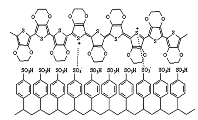
Figure 24: Structure of PEDOT:PSSA
The discovery that PEDOT:PSSA could improve breakdown voltage was a breakthrough in technology. The disadvantage of this pre-polymerized material is that it is more difficult to impregnate into the pores of the anode pellet and incomplete contact with the dielectric oxide surface will result in not achieving the wet capacitance of the anode. This is commonly called ‘wet to solid’ loss and is present to varying degrees for MnO2 cathodes and conductive polymer cathodes prepared by in-situ chemical polymerization, electrochemical polymerization, and deposition from a pre-polymerized dispersion. Manufacturers of pre-polymerized conductive polymer dispersions have introduced materials with smaller particles to partially overcome this issue36. We can add an additional term to Equation 5, Cs/Cw which represents this loss as a ratio of the capacitance after impregnation by the solid cathode to the wet capacitance that would be measured in a liquid electrolyte (which is assumed to contact the entire dielectric surface):
$$ \frac{C_{s}V_{r}}{{Vol}_{a}} = \frac{C_{w}V_{f}}{g} \times \rho_{s} \times \frac{V_{r}}{V_{f}} \times \frac{C_{s}}{C_{w}}\tag{8}$$
Wet to solid losses of less than 10% (Cs/Cw >90%) are desirable, but for higher charge powders and larger anode pellets this is sometimes not achievable.
Tantalum-Polymer capacitors are more sensitive to environmental factors than tantalum-MnO2 capacitors. While MnO2 is temperature stable to several hundred-degree Celsius, conductive polymers show significant degradation at temperatures below 200°C in an inert atmosphere and less than 150°C in air (PEDOT is more stable than polypyrrole). This can cause capacitance loss and ESR increases on long-term temperature exposure.
Early in conductive polymer development it was discovered that organic sulfonic acids were the most thermally stable dopants for conductive polymers37. Later PEDOT was developed as a more stable conductive polymer than polypyrrole38. Jin et al. discovered that conductive polymers prepared from pre-polymerized dispersions were more thermally stable than those prepared via in-situ chemical polymerization39.
Conductive polymers are affected by moisture which can cause swelling of the polymer and cause impurities that are used in synthesizing them to leach out. Moisture absorption can cause ‘popcorning’ of parts during surface mount reflow and variations in capacitance in a humid environment and determines how long the parts can be exposed outside the moisture bag packaging before use (MSL level). It can also cause corrosion of the silver metal coatings and metal lead frame materials. The hydrophilicity of the conductive polymer is due to the ionic dopants like para-toluene sulfonic acid (in-situ chemical polymerization) and polystyrene sulfonic acid (pre-polymerized). Bunha et al. have developed dopant systems with more hydrophobic dopants that partially address this issue40.
In the next section on packaging, I’ll discuss how packaging design can help overcome some of these environmental sensitivities of tantalum-polymer capacitors.
Packaging and Environmental Resistance
Packaging—the attachment of the capacitor to external leads and placing some protection around the capacitor element so it will remain electrically in-specification after soldering to the circuit board and during use in the intended environment— is a key part of the process. Figure 7(b) shows the standard “gull-wing” style of surface mount packaging that is used for both tantalum-MnO2 and tantalum-polymer capacitors. It has been in use for more than 35 years and is a mature way of packaging a tantalum capacitor. The disadvantage of this type of packaging is that the active capacitor element is only a small part of the volume of the package. We can rewrite Equation 8 with this additional term as:
$$ \frac{C_{s}V_{r}}{{Vol}_{pkg}} = \frac{C_{w}V_{f}}{g} \times \rho_{s} \times \frac{V_{r}}{V_{f}} \times \ \frac{C_{s}}{C_{w}} \times \frac{{Vol}_{a}}{{Vol}_{pkg}}\tag{9}$$
where now we calculate the charge storage capability relative to the package volume (Volpkg) instead of the anode volume (Vola). The package volume includes any material outside the interior of the anode pellet (external cathode, carbon, silver, silver adhesive, lead frame, and epoxy). This introduces a new term Vola/Volpkg which I call the “packaging efficiency”. Larger packages tend to have more active volume (higher packaging efficiency) and smaller one’s lower packaging efficiency. For a 3.5x2.8x1.2mm package (1.2 mm height B case) in the gull-wing style of Figure 7(b), it is quite low about 0.2 (or 20% packaging efficiency). Manufacturers of tantalum capacitors have developed more efficient packaging to address this issue.
Figure 25 shows the efficiency of two new packaging styles as compared to the gull-wing style. The face-down style moves the anode and cathode lead frames to the bottom of the package. Some modest increase in packaging efficiency is achieved through employing this design. The solder is confined to underneath the part so there are no solder fillets on the side of the package which potentially allows components to be placed closer together which achieves greater packaging efficiency at the board level. The downside is that it is harder to use AOI to inspect the quality of the solder joints. The leadless design eliminates the lead frame and directly connects the positive tantalum lead wire and cathode silver paint to plated terminals. This design achieves a much higher packaging efficiency than either the gull-wing or face-down style. It has only recently been introduced in large-volume commercial production.

Figure 25: Surface Mount Tantalum Capacitor Packaging Styles (Efficiencies for 3.5x2.8x1.2mm package size)
The original high-volume application for tantalum-polymer capacitors was notebook (laptop) computers. This is a relatively benign environment and 105°C rated components with moderate humidity resistance are acceptable in this application. Manufacturers pushed for additional applications such as automotive, datacenter servers, and defense/aerospace where environments are considerably more severe, and lifetime requirements are more stringent. This required an improvement in the stability of the tantalum-polymer capacitor against increases in leakage current, capacitance loss, and increased ESR against temperature, humidity, and thermal shock. This is accomplished by both improving the properties of the conductive polymer and protecting the conductive polymer, silver coating, and lead frame through packaging improvements.
Figure 26 shows the mechanism of ESR increase and leakage increase (to short circuit) when tantalum-polymer capacitors are exposed to a high temperature and humidity environment41. Typical accelerated test conditions for tantalum-polymer capacitors are 60°C/90%RH and 85°C/85%RH for 1000 hours. A highly accelerated stress test (HAST) is sometimes performed at 121°C/85%RH for 24 to 72 hours. These tests can be done unbiased or with voltage applied. During this exposure moisture penetrates through the epoxy case and along the lead frame-epoxy interface into the interior. The conductive polymer material is susceptible to moisture uptake because of the ionic dopants that are part of the polymer or impurities left in the part from the polymerization process. This can cause the conductive polymer to swell resulting in separation of the polymer layers and ESR increase. There is also some evidence that after this separation the conductive polymer can lose its dopant when the humidity test is done with bias. De-doping would cause regions of the conductive polymer to become non-conductive. ESR increases also can result in loss of capacitance, if the conductive polymer in the interior of the anode pellet separates or becomes non-conductive.
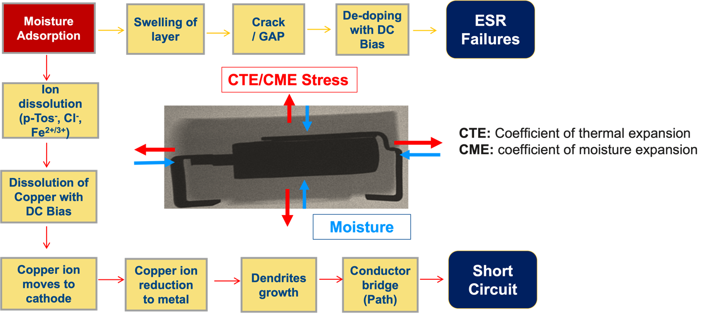
Figure 26: Mechanisms of ESR and Short Circuit Failures under High Temperature/Humidity Conditions in Tantalum-Polymer Capacitors
The ionic dopants in the conductive polymer, ionic species from the epoxy case (like chloride), and residual polymerization reactants (like ferric ions) dissolve in the moisture that penetrates to the interior of the epoxy case and form an electrolyte solution. This electrolyte solution can bridge between copper in the anode lead frame and the conductive polymer cathode. Under voltage bias, the copper metal can corrode to copper ions and migrate to the cathode where it can redeposit as copper metal. This can bridge the area between the anode and cathode with conductive metal shorting the capacitor. Another mechanism of corrosion (not shown in Figure 26) is the dissolution of the cathode silver coating to silver ions which can migrate through the carbon and react with the conductive polymer to redeposit as silver metal. If the silver metal touches the dielectric, it can also cause a short circuit. This mechanism usually occurs in an unbiased environment.
To mitigate these mechanisms that cause ESR increase and short circuits during temperature/humidity exposure, manufacturers of tantalum-polymer capacitors developed several solutions:
Use of lower moisture permeability epoxy molding compound.
Use an epoxy molding compounds with a lower amount of leachable ionic impurities.
Use a moisture barrier coating between the epoxy case and internal elements42.
Make the conductive polymer more hydrophobic31.
Make a better bond between the lead frame and epoxy molding compound.
Reduce the ionic contaminants through better removal of excess reactants/waste products from the polymerization reaction.
Use a lead frame material that is more corrosion resistant (substituting, for example, iron or nickel for part or all the copper).
Increase the distance between the anode and cathode by removing any residual polymer from the tantalum lead wire.
Make a stronger bond between the multiple conductive polymer layers43.
Use a hermetically sealed package44.
The stability of tantalum-polymer capacitors in high temperature (dry) environments is also of interest. These environments are relevant to automotive and defense/aerospace applications where electronics may be intermittently exposed to high temperatures while vehicles and equipment are in operation and in data centers where temperatures are somewhat lower, but operation is on a continuous 24/7 basis. The Dielectric section covered degradation of the dielectric under these conditions, but as noted above, the conductive polymer can also degrade via thermal de-doping or oxidation of the conjugated polymer backbone. Two strategies are adopted to mitigate these effects: 1. Develop more intrinsically thermally stable conductive polymer systems (discussed in the Cathode section), and 2. Limit the contact of oxygen with the conductive polymer. Chacko et al. developed methods to limit air ingress via packaging design and development of protective coatings45.
Because of these advances in temperature and temperature/humidity resistance of tantalum-polymer capacitors, product series are now available for automotive applications46, and for defense/aerospace applications47.
Reliability
Early applications of solid tantalum capacitors were in segments such as defense, aerospace, and automotive, and high reliability was a key characteristic. Early on the discovery that failure rates for tantalum capacitors with a MnO2 cathode were not constant but declined upon application of voltage and temperature over time led to ‘grading’ of tantalum capacitors in the factory before shipment and established reliability levels for high reliability applications48. Here reliability means the capacitor not failing as a short circuit under temperature and voltage stress.
With the invention and subsequent application of the tantalum-polymer capacitor, questions naturally arose about their reliability, especially as applications expanded from the original applications in notebook computers and consumer devices to automotive, data center, defense, and aerospace. Reed and co-workers performed extensive testing of tantalum-polymer capacitors under accelerated voltage and temperature conditions and developed models for dielectric wear-out (to short circuit) in these devices49. The tantalum-polymer parts failed by wear-out over a narrow range of times. The devices proved to be very reliable; extrapolation to rated voltage and 85°C operating conditions predicted tens to hundreds of thousands of hours of lifetime. By combining improvements in tantalum anode technology with conductive polymer cathode technology discussed in the previous sections, this lifetime to dielectric wear out can be extended even further50.
As noted in the previous sections, tantalum-polymer capacitors are susceptible to ESR increases due to de-doping or oxidation of the polymer at elevated temperatures. This, and not dielectric wear out could be the limiting factor in their lifetime. Teverovsky modeled this degradation mechanism in commercial and automotive grade tantalum-polymer capacitors51. Automotive grade devices showed longer times to ESR increases outside the manufacturer’s specification (which can be several times the initial ESR specification).
The humidity behavior of tantalum-polymer capacitors is complex because there are several mechanisms that cause degradation of ESR and corrosion that can lead to short circuits. Good predictive models for degradation in humid environments are not yet available for tantalum-polymer capacitors.
Technology Challenges
Despite the success of tantalum-polymer capacitors in the market, some current and (potential) future material and performance challenges need to be addressed. One phenomenon is ‘anomalous charging’ which was first reported by Dr. Yuri Freeman52. For an ideal capacitor, charging current is given by:
$$i = C\frac{dV}{dt}\tag{10}$$
where i is the charging current, C is the capacitance and dV/dt is the rate of voltage change. In anomalous charging, the current exceeds this ideal current (often by several times). This is particularly a problem upon circuit start-up in power systems where voltage may be ramped up at a high rate and the power supply is not capable of delivering this anomalous current. The anomalous current is affected by several factors particularly the moisture level in the capacitor (low moisture is worse) and temperature (low temperature is worse). This is particularly a concern in space applications where temperature extremes and a dry environment (due to vacuum) are prevalent. Dr. Teverovsky at NASA has extensively studied this phenomenon53. Manufacturers such as AVX54 and KEMET55 have developed tantalum-polymer capacitors with lower anomalous currents, but a firmer theoretical understanding of the mechanism is needed to make further progress.
Materials used in electronic devices are subject to government regulation. Tantalum is already classified as a ‘conflict mineral’ and the sourcing of tantalum ore is regulated by government and industry organizations. Restrictions on other materials are covered by, for example, REACH and RoHS regulations. A recent initiative by the European Union and other authorities around the world is the elimination of “PFAS” materials from products (not limited to electronics). Manufacturers of electronic devices are asking suppliers to eliminate these materials in their components to avoid supply chain disruptions when the regulations come into effect. The exact definition of these materials is highly technical, but basically, they are molecules (short-chain and polymer) that contain fluorine. Fluorine-containing compounds are known for their hydrophobicity and low surface energy, and therefore, are used in many compounds that repel water and prevent sticking. In tantalum capacitors they are used for tantalum lead wire protection and as part of moisture barrier coatings. Manufacturers are now working diligently to substitute other materials for PFAS-containing substances to meet customer and government timelines. This is a major materials science challenge as fluoro-containing materials have properties that are difficult to match with other compounds.
A growth area for the use of tantalum-polymer capacitors is in power management circuits for CPU/GPU in data centers. Power levels of these processors, in particular GPUs continue to increase with individual GPUs reaching 1kW and multi-GPU racks tens of kilowatts. The power is dissipated as heat which must be removed to keep the operating temperatures low enough to avoid damage to the GPU and surrounding components (memory, MOSFETs, power controllers, and passives such as capacitors, inductors, and resistors). Currently this is done by blowing air over the racks. As power levels continue to increase, this may no longer be sufficient, and manufacturers of the GPUs and data center operators are looking at alternative means of cooling such as direct liquid cooling via cold plates and even immersing entire server racks in a dielectric fluid to cool them (immersion cooling). If immersion cooling is adopted, then components will be directly exposed to the fluid and must not degrade electrically or mechanically after long-term exposure or leach any substances into the fluid that cause it to degrade. Both one-phase and two-phase immersion cooling are being considered. The one-phase fluids are hydrocarbon-based, and the two-phase fluids are currently fluorocarbon-based (although that might change due to PFAS regulations). Component manufacturers are working with CPU/GPU suppliers to test the compatibility of their components with these fluids. This includes tantalum capacitor manufacturers.
Conclusions
Despite the challenges from other dielectric technologies, tantalum capacitors continue to be widely used in electronic devices. Figure 27 shows that while overall tantalum capacitor market value has remained relatively flat, for several years now (except for the dot-com bubble in 2000), the relative share of tantalum-polymer technology has continued to grow. Its share surpassed that of the tantalum-MnO2 type in 2019 and continues to increase.
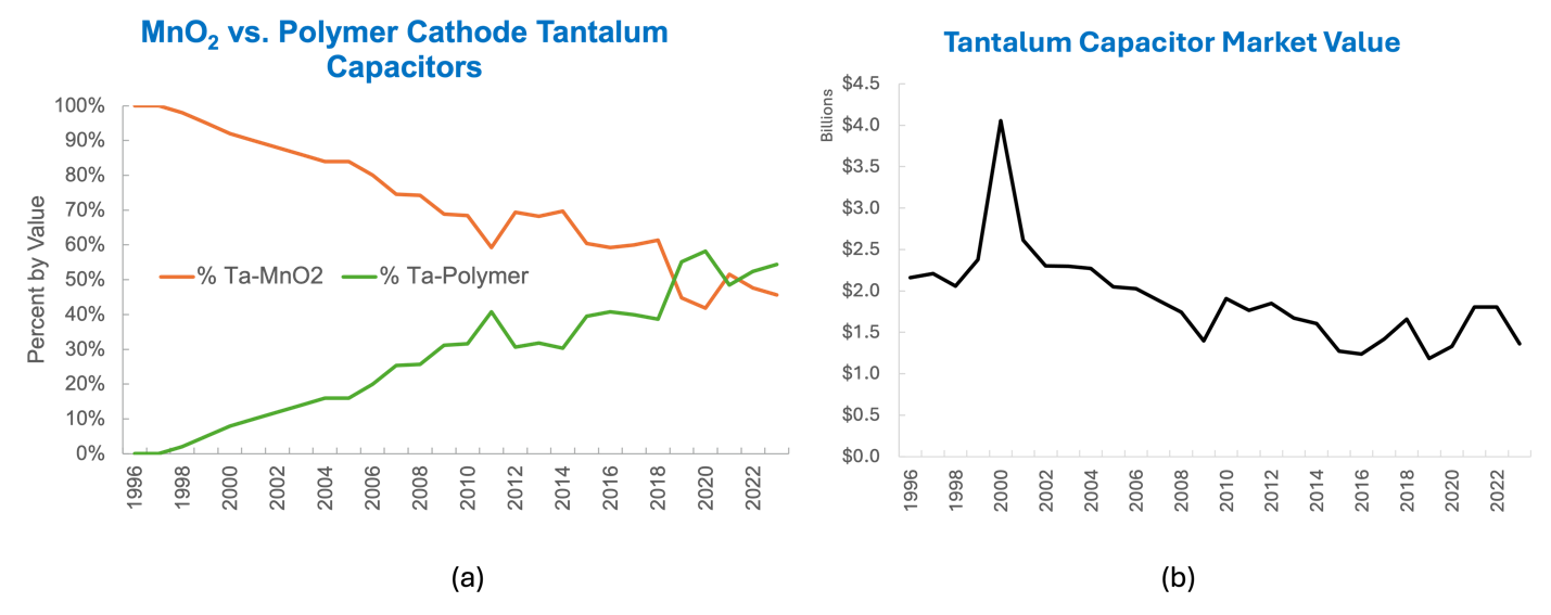
Figure 27: (a) MnO2 and Polymer Cathode Market Share (b) Overall Tantalum Capacitor Market Value
Tantalum capacitors support electronics in all market segments, and Figure 28 shows an approximate breakdown of revenue by segment. Computers (primarily notebook/laptop computers) continue to be the dominant application for tantalum-polymer capacitors, but with the advances in reliability and environmental stability of these devices, segments such as automotive, data center (telecom/cloud), and military/aerospace continue to grow.
The future for tantalum capacitors is indeed bright.

Figure 28: Revenue by Market Segment
References
V. Macagno and J.W. Schultze, “The Growth and Properties of Thin Oxide Layers on Tantalum Electrodes,” J. Electroanal. Chem., 180, 157 (1984).↩︎
J. Prymak, "Spice Models of Capacitors," KEMET Tech Topics, 4(5) (September 1994).↩︎
https://ksim3.kemet.com/capacitor-simulation, https://spicat.kyocera-avx.com/Tan, https://www.vishay.com/en/capacitors/vita-spice/ , https://industrial.panasonic.com/ww/downloads/simulation-data/poscap.↩︎
P. Robinson, “Electrical Capacitors,” US Patent 3,066,247 (November 27, 1962), R.J. Millard, “Electrolytic Device”, US Patent 2,936,514 (May 17, 1960).↩︎
H.E. Haring and R.L. Taylor, “Dry Electrolytic Device”, US Patent 3,166,693 (January 19, 1965).↩︎
H. Shirakawa et al., “Synthesis of Electrically Conducting Organic Polymers: Halogen Derivatives of Polyacetylene (CH)x,” J. Chem. Soc., Chem. Commun., 578 (1977).↩︎
Y. Kudoh et al., “A Highly Thermostable Aluminum Solid Electrolytic Capacitor with an Electroconducting-Polymer Electrolyte,” in M. Aldissi, (ed.) Intrinsically Conducting Polymers: An Emerging Technology, Kluwer Academic Publishers, p. 191 (1993).↩︎
T. Fukaumi et al., “Polymer Tantalum Capacitor,” NEC Technical Journal, 46(12) (1993).↩︎
Dissipation factor (DF) or loss tangent is the ratio of ESR to capacitive reactance--DF = 2πfC × ESR↩︎
Y. Freeman, Tantalum and Niobium-Based Capacitors, page 54, 2nd Ed., Springer, 2022.↩︎
Y. Pozdeev-Freeman et al., “Critical Oxygen Content in Porous Anodes of Solid Tantalum Capacitors,” Journal of Materials Science: Materials in Electronics, 9, 309 (1998). Y. Pozdeev-Freeman et al., “Effect of Dissolved Oxygen on Thermal Oxidation in Ta2O5/Ta Sandwiches,” Journal of Electronic Materials, 27, 1034 (1998). Y. Pozdeev-Freeman and A. Gladkikh, “Effect of Thermal Oxide on the Crystallization of the Anodic Ta2O5 Film,” Journal of Electronic Materials, 30, 931 (2001).↩︎
M. Hagymási et al., “Pushing Tantalum Capacitors to the Limit: A Powder Manufacturers View To 300V
Anodizations and Beyond,” 3rd Space Passive Component Days (SPCD), International Symposium, The Netherlands (2018).↩︎
Y. Pozdeev-Freeman, “Method for Doping Sintered Tantalum and Niobium Pellets with Nitrogen,” US Patent 6,410,083B1 (June 25, 2002). Y. Pozdeev-Freeman, “Sintered Tantalum and Niobium Capacitor Pellets Doped with Nitrogen, and Method of Making the Same,” US Patent 6,447,570B1 (September 10, 2002). Y. Pozdeev-Freeman, “How Far Can We Go with High CV Tantalum Capacitors,” Passive Component Industry, p. 6 (January/February 2005).↩︎
Y. Freeman et al., “Low Voltage CV/g Loss in Ta Capacitors,” J. Electrochem. Soc., 157, G161 (2010).↩︎
D. M. Smyth, G. A. Shirn, and T. B. Tripp, “Heat Treatment of Anodic Films on Tantalum: 1. Effects on the Dielectric Properties,” J. Electrochem. Soc., 110 (12), 1264 (1963). D.M. Smyth and T.B. Tripp, “Heat Treatment of Anodic Films on Tantalum: II. Temperature Dependence of Capacitance,” J. Electrochem. Soc., 110 (12), 1271 (1963). D. M. Smyth, G. A. Shirn, and T. B. Tripp, “Heat Treatment of Anodic Films on Tantalum: 1. The Conductivity Profile,” J. Electrochem. Soc., 111 (12), 1331 (1964). D. M. Smyth, G. A. Shirn, and T. B. Tripp, “Heat Treatment of Anodic Films on Tantalum: IV. Anodization in Phosphoric Acid Solutions,” J. Electrochem. Soc., 113 (2), 100 (1966). D. M. Smyth, “Heat Treatment of Anodic Films on Tantalum: V. The Thermal Redistribution of Incorporated Phosphorous,” J. Electrochem. Soc., 113 (12), 1371 (1966). D. M. Smyth, “Heat Treatment of Anodic Films on Tantalum: VI. The Effect of Chemical Thinning,” J. Electrochem. Soc., 114 (7), 723 (1967).↩︎
G. Klein, “Oxidation State of Anodic Tantalum Oxide after Heat Treatment I. Galvanostatic Method as Applied after Heating in Vacuum,” J. Electrochem. Soc., 119(11), 1551 (1972).↩︎
D. A. Vermilyea, “Nucleation of Crystalline Ta2O5 During Field Crystallization,” J. Electrochem. Soc., 104(9), 542 (1957), Y. Freeman, Tantalum and Niobium-Based Capacitors, page 9, 2nd Ed., Springer, 2022.↩︎
Y. Pozdeev-Freeman et al., “Effect of Dissolved Oxygen on Thermal Oxidation in Ta2O5/Ta Sandwiches,” Journal of Electronic Materials, 27, 1034 (1998).↩︎
J.J. Randall Jr., W.J. Bernard, and R.L. Wilkinson, “A Radiotracer Study of the Composition and Properties of Anodic Oxide Films on Tantalum and Niobium,” Electrochimica Acta, 10, 183 (1965).↩︎
J.D. Sloppy, “Anodization Mechanism and Properties of Bi-Layer Tantalum Oxide Formed in Phosphoric Acid,” PhD Dissertation, Pennsylvania State University (2009). J.D. Sloppy et al., “Growth Laws of Bilayer Anodized Tantalum Oxide Films Formed in Phosphoric Acid,” J. Electrochem. Soc., 157(5), C157 (2010). J.D. Sloppy et al., “Growth mechanism of anodic tantalum pentoxide formed in phosphoric acid,” Electrochimica Acta, 87, 82 (2013).↩︎
J.T. Kinard and B. Melody, “Method of Anodizing a Metal Anode Prepared from Very Fine Metal Powder,” US Patent 6,162,345A (December 19, 2000).↩︎
B. Melody, J.T. Kinard, and D. Wheeler, “Anodizing Electrolyte and its Use”, US Patent 5,716,511A (February 10, 1998).↩︎
W. Bernard and S. Szpak, “Two-stage anodization of capacitor electrodes,” US Patent 4,131,520A (December 26, 1978).↩︎
B. Melody et al., “Differential anodization process for electrolytic capacitor anode bodies,” US Patent 6,261,434B1 (July 17, 2001).↩︎
P. Winkel and D.G. de Groot, "Impedance of Dielectric Layers," Philips Res. Reports, 13, 489 (1958). D.A. McLean, "The A-C Properties of Tantalum Solid Electrolytic Capacitors,” J. Electrochem. Soc., 108, 48 (1961). B. Goudswaard, "The Equivalent Series Resistance of Tantalum Solid Electrolytic Capacitors," Electrochem. Tech., 6, 178 (1968).↩︎
R. Hahn et al., “Tantalum Capacitor Impregnation Process,” US Patent 5,622,746 (April 22, 1997).↩︎
J. Piper, “Electrolytic Capacitor with Separate Interconnected Anode Bodies,” US Patent 3,686,535 (August 22, 1972).↩︎
I. Horacek, et al., “Improved ESR on MnO2 Tantalum Capacitors at Wide Voltage Range,” accessed at https://kyocera-avx.com/docs/techinfo/Tantalum-NiobiumCapacitors/impesr.pdf↩︎
K. Sakata et al., “Solid Electrolytic Capacitor with Conductive Polymer as Solid Electrolyte and Method for Fabricating the Same,” US Patent 5,729,428 (March 17, 1998).↩︎
K. Araki et al., “Development of NEOCAPACITOR PSL Series,” NEC Technical Journal, 51(10) (1998).↩︎
F. Jonas et al., “Solid Electrolytes, and Electrolyte Capacitors Containing Same,” US Patent 4,910,645A (March 20, 1990).↩︎
J. Prymak, “Improvements in Polymer Cathodes in Tantalum and Aluminum Capacitors,” 16th Annual IEEE Applied Power Electronics Conference and Exposition (2001).↩︎
Y. Freeman et al., “Electrical Characterization of High Voltage Polymer Tantalum Capacitors,” J. Electrochem. Soc., 159(10), A1646 (2012).↩︎
A. Elschner et al., PEDOT Principles and Applications of an Intrinsically Conductive Polymer, Chapter 9, CRC Press (2011).↩︎
Y. Qiu, R. Hahn, and K. Brenneman, “High Voltage Solid Electrolytic Capacitors Using Conductive Polymer Slurries,” US Patent 7,563,290B2 and US Patent 7,990,683B2 (2009 and 2011).↩︎
U. Merker et al., Process for the Production of Electrolyte Capacitors,” US Patent 8,058,135B2 (November 15, 2011).↩︎
Y. Kudoh et al., “An Aluminum Solid Electrolytic Capacitor with an Electroconducting Polymer Electrolyte,” Synthetic Metals, 41-43, 1133 (1991).↩︎
Y. Kudoh et al., “Solid electrolytic capacitor with highly stable conducting polymer as a counter electrode,” Synthetic Metals, 102, 973 (1999).↩︎
Y. Jin et al., “Thermal Stability Investigation of PEDOT Films from Chemical Oxidation and Prepolymerized Dispersion,” Electrochemistry, 81(10), 801 (2013).↩︎
A. Bunha et al., “Polyanion copolymers for use with conducting polymers in solid electrolytic capacitors,” US Patent 10,340,091 (July 2, 2019).↩︎
A. Chacko et al., “Advances in Reliability of Conducting Polymers and Conducting Polymer Based Capacitors in High Humidity Environment”, ECS Transactions, 85 (13) 115 (2018).↩︎
Y. Liu et al., “Solid Electrolytic Capacitor,” US Patent 9,293,263B2 (March 22, 2016).↩︎
A. Chacko and D. Hui, “Solid electrolytic capacitor with interlayer crosslinking,” US Patent 9,312,074 (April 12, 2016) and US Patent 9,941,055 (April 10, 2018).↩︎
https://www.kemet.com/en/us/technical-resources/polymer-hermetic-seal-capacitors.html, https://www.kyocera-avx.com/products/polymer/high-reliability-polymers/tch-hermetically-sealed-polymer/.↩︎
A. Chacko et al., “Development of High Temperature Tantalum Polymer Capacitors,” Proceedings of the 51st International Symposium on Microelectronics, IMAPS, (2018).↩︎
Jayson Young and Javaid Qazi, “Polymer Tantalum Capacitors for Automotive Applications,” CARTS International (2014). J. Ye et al., “Conductive Polymer Based Tantalum Capacitor for Automotive Applications,” T.I.C. 56th General Assembly (2015).↩︎
https://www.kemet.com/en/us/capacitors/polymer/polymer-high-reliability.html Accessed August 18, 2024. https://content.kemet.com/datasheets/KEM_T2090_T580-581.pdf, Accessed August 18, 2024.↩︎
D.E Maguire, “Expressing Capacitor Reliability Accurately,” Electronic Industries, (December 1962). G.H. Didinger, Jr., “Tantalum Capacitor Accelerated Life Testing, Evaluation Engineering, (December 1964). H.W. Holland, “The Impact of Established Reliability Specification MIL-C-39003 on Solid Tantalum Capacitors,” Evaluation Engineering, 7(1) (Jan-Feb 1968).↩︎
J. Paulsen et al., “Reliability of Tantalum Polymer Capacitors,” CARTS Conference, San Antonio, TX (2004). E. Reed and G. Haddox, “Reliability of High Voltage Tantalum Polymer Capacitors,” CARTS Conference, Jacksonville, FL (2011).↩︎
Y. Freeman and P. Lessner, “Evolution of Polymer Tantalum Capacitors,” Appl. Sci., 11, 5514 (2021).↩︎
A. Teverovsky, “Effect of High Temperature Storage on AC Characteristics of Polymer Tantalum Capacitors,” Journal of Microelectronics and Electronic Packaging, 18, 177, (2021).↩︎
Y. Freeman et al., “Anomalous Currents in Low Voltage Polymer Tantalum Capacitors,” ECS Journal of Solid State Science and Technology, 2(11), N197 (2013).↩︎
A. Teverovsky, “Metrics for Anomalous Charging Currents in Polymer Tantalum Capacitors,” IEEE Electrical Insulation Conference (EIC), p. 1 (2023).↩︎
J. Petržílek et al., “Polymer Tantalum Capacitors with Suppressed Transient Current,” accessed at https://www.kyocera-avx.com/docs/techinfo/Tantalum-NiobiumCapacitors/Poly-Tant-Caps-Suppressed-Transient.pdf↩︎
A. Chacko et al., “Capacitor with Charge Time Reducing Additives and Work Function Modifiers,” US Patent 9,793,058B2 (October 17, 2017).↩︎